RF Admittance Level Sensor (SFC5 Series) — Installation and Operation Guide
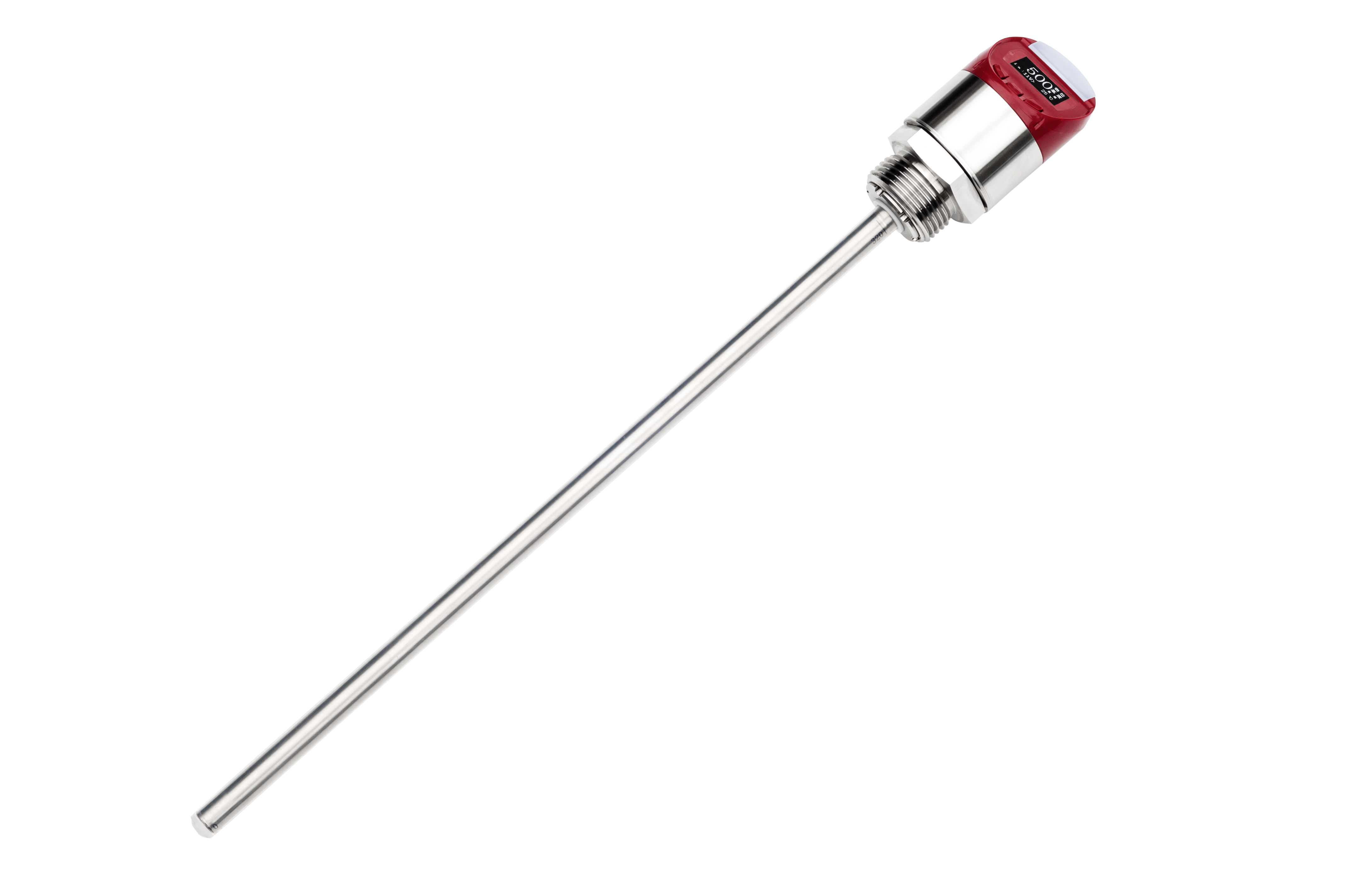
The RF Admittance Level Sensor (SFC5 Series) developed by Shenzhen Soway Tech Limited (Soway) is an industrial-grade solution for precise and stable level detection in complex media. Based on radio frequency admittance technology, it measures both capacitance and resistance between the probe and the tank wall, effectively compensating for buildup or coating on the electrode to ensure long-term stability.
Installation and Setup
Before installation, check that the package includes the sensor body, probe assembly, and mounting accessories. Inspect all parts for damage. The sensor is typically installed on the tank top or side wall, depending on the application. For viscous or high-temperature materials, the split-probe version is recommended, while the integrated version suits general industrial use.
Ensure the probe does not touch the tank wall or internal components. Standard threaded or flange mounting options are available. Proper grounding is essential to avoid static interference and ensure reliable signal output.
For electrical wiring, use shielded cables to minimize electromagnetic interference. Connect the power supply (9–36V DC) and output terminals (4–20mA, 0.5–4.5V, or RS485 Modbus) according to the system configuration. Verify all terminal connections and grounding.
Calibration and Configuration
Each RF Admittance Level Sensor is factory-calibrated, but on-site calibration may be performed for greater precision.
To set the zero point, keep the probe in air and press the “ZERO” button until the indicator flashes.
For full-scale calibration, immerse the probe to the maximum level and press the “SPAN” button. After calibration, verify the output value.
If equipped with a local display gauge, the unit can show real-time level readings or percentage values. Users can configure display units, set alarm points, or adjust parameters through the interface.
Operation and Maintenance
During operation, the sensor continuously analyzes admittance (the inverse of impedance) to provide stable readings, even when the medium forms a coating layer. This design minimizes manual cleaning and ensures dependable operation in challenging environments.
For reliable performance, keep the probe clean, verify calibration periodically, and protect terminals from moisture and dust. Avoid routing signal cables near high-voltage lines to prevent electrical interference.
Troubleshooting
If no signal is detected, check wiring and power supply.
Fluctuating readings often result from grounding or EMI issues—use shielded cables.
Output deviation may indicate recalibration is required.
For RS485 communication, confirm Modbus address and baud rate settings.